Monday, April 28, 2008

Arrays


Single Dimensional (1D).


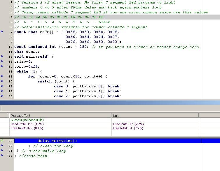
Key in the code below. I know it is long…But there is a point to this. This is to show you how to eliminate redundant code. After keying in the code and compiling it and correcting your typing errors; burn it to your PIC. Connect a common cathode (or common anode) 7 segment LED to portB. When the PIC is powered up, you will see the number 0, 1, ..9 displayed in a endless loop.


Lesson 4 Ver 1 Page 1

Lesson 4 Ver 1 Page 2

Lesson 4v1 compiled


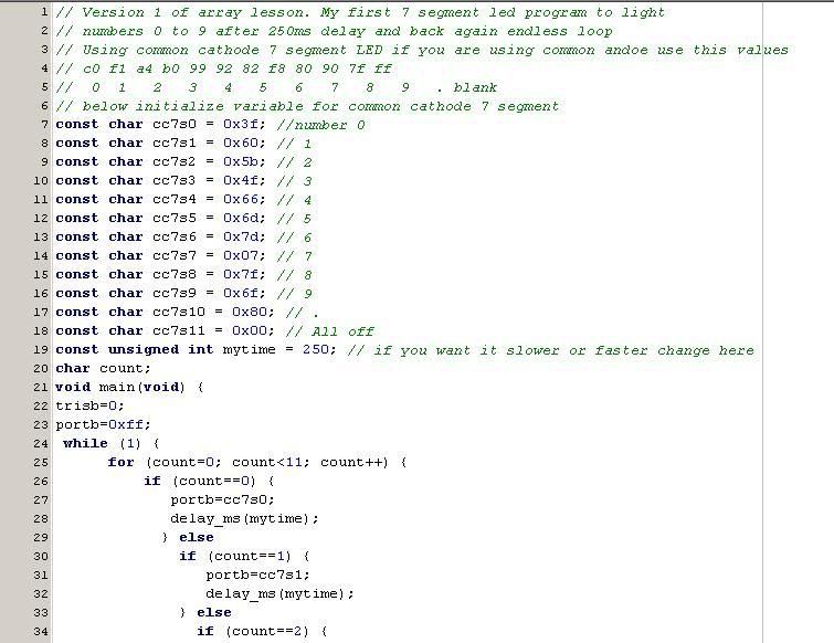
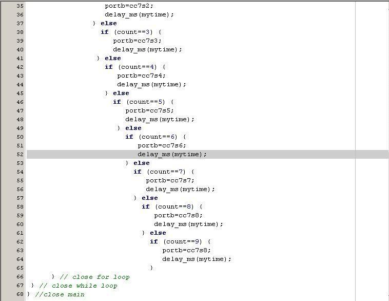
Actually this is an example of bad programming. The code is large, it’s time consuming and the chances of making typos is high. I will now demonstrate arrays. This is how to define arrays:-

char name[30]; //This is an array of 30 characters.

double tempC[10]; // Array of 10 floating point numbers

int x[5]; // An array of 5 elements that can hold 5 signed int.

It like defining 5 variables.
x[0] can store a value x[1] can store another and so on.
x is a variable or const, and [0] is the location where the value is stored.


Also important to note:

the [] in arrays do not mean optional, as it usually does in documentation standard.
the first element of array is always 0.
arrays can be of any valid C data type, ie, float, double, int or char.


If you want to load the array with known values, do this when you declare you array:-

char base2[6] = {1, 2, 4, 8, 16, 32};

This array holds 6 elements, base2[0] is 1, base2[1] is 2, etc. etc. etc..

Or you can do this:-

unsigned int base2[]={1,2,4,8,16,32,64,128,256,512,1024};

When you don’t specify number of elements, and when you compile the, compiler will count then number of element and assign 0 to the first element, 1 to the next one and so on.

Following me so far….Excellent!

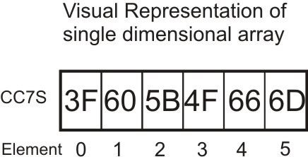
Firstly let’s use a variable cc7s as an array of chars. I set is as constant because the values will not change.

The point to this is that the code can be modified using arrays. Using the same code (new project, copy and paste), then change with the modifications in listing below.


Lesson 4 Ver 2 Page 1

Lesson 4v2 compiled


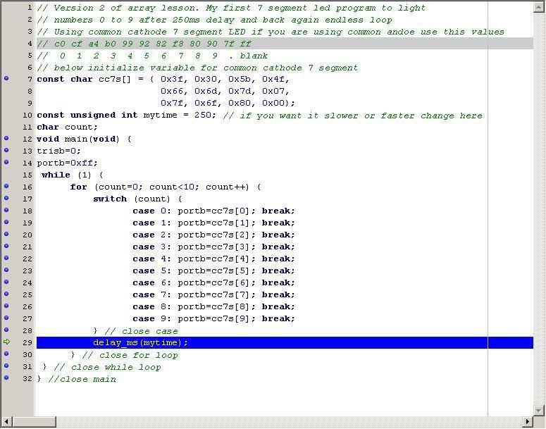
OK, All i have done is replaced the variables with arrays and if() with case. Some what smaller code. But wait! I see a pattern! when count==0, cc7s[0] is displayed, when count==1, cc7s[1] is displayed and so on. Then it loops back and starts over. So, lets redo the Version 1 and 2 code. Type in the listing below.

Note: switch..case will be explained in a later chapter..


Lesson 4 Ver 3 compiled


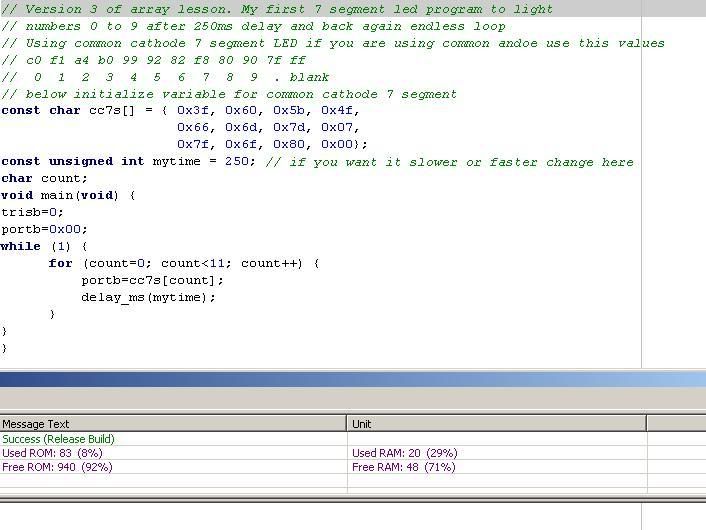
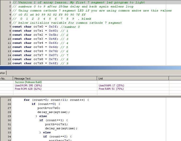
And that my dear students, is how you use arrays. It compiled to 83 bytes, as compared to 395 bytes in version 1. That’s almost 5 times smaller.


Let’s see if you understood the above lesson.

Skill Check!

1. Declare an array called DOW and initialize it’s elements with first 3 characters of day of week beginning with Monday.

2. What would need to do:-

a) To display decimal point with ALL the numbers.

b) To display decimal point ONLY with odd numbers.

c) To display decimal point ONLY with even number.

Only display decimal point, not to blink it.

Hint: You’ll need to refer to previous lessons.

3. Write a program to display number from 0 to 9 in an endless loop. Turn on the decimal point for 150ms and then off it for 150ms for every number.

4. Without changing the values of the arrays in the version 3 program, modify the program to display the numbers from 0 to 9 on a common anode 7 segment LED. (If you are already using a common anode, then do for common cathode).

Hint: Common cathode is opposite of common anode.

Wednesday, April 23, 2008

Let's C... Some ADC... 4U2C...


Updated:

After some of you got a little sober after the smooth operator 60s' twists, here's an an example of ADC usage in MikroC.

The codes are commented so you should roughly knows what the codes is all about and what each line is doing. I'll do a write up on ADC on the next post. In most cases, some form of scaling is required so some understanding of ADC reference voltage is crucial.

How the board is wired up for the lesson... noticed the purposed-built LCD ribbon cable?

Update 080425: A short brief on ADC.
PIC18F4550 (and most ADC capable PIC) has a 10-bit ADC core. The ADC is based on analog reading between VRef- to VRef+. When input is at VRef-, the value returned will be 0 (zero) and when input is at VRef+, the value returned will be 1023 (2^10 - 1, i.e., 2 to the power of 10 minus 1).
In the current example, via setting done with ADCON1, VRef- is set to VSS (GND) and VRef+ is set to VDD (+5V). Under this environment, the resolution of the ADC is +5V/1024 = about 5mV. When the potentiometer is at minimum (0V) the result is 0 and when at maximum (+5V) the result is 1023. To get the actual voltage reading, you need to do scaling, the math as follows:
Actual Voltage = (ADC Reading * Value at VRef+) / 1024
i.e., if result is 512, then the actual voltage is 512 * 5 / 1024 = 2.5V

If you need higher resolution, you can provide the PIC with your own VRef- & VRef+ directly to the AN2 & AN3 pins. Change ADCON1 settings to 0b00111011. If you set VRef+ to about 1V, the resolution becomes 1mV (1V/1024).

For quick reference, ADCON1 setting information is below:

On PIC18F4550, the analog pins are on 3 separate ports... do your own searching below... Remember to set TRISA, TRISB, TRISE and ADCON1 configuration accordingly...

Smooth Operators

Relational operators.

Relational operators are used indecision making. There are 6 different type of operator at your disposal. They are:-

Op

Comment

==

is equal to

!=

not equal to

<

less than

<=

less than OR equals to

>

more than

>=

more than OR equals to


These operators are used in loops, if(), while, for() or where ever is decision needs to be made. Take care when using this. Example if you want the loop to perform 4 cycles, writing a for loop for example:

for (x=1; x<4; x =4;x++); This only preform 3 iterations (loops), because when x=4, the condition will be false. 4<4, No 4 is equal to 4. So to overcome this problem, use x<=4 or x<5. This will achieve the result you want of 4 loops

Bit operators

&

AND

|

OR

~

NOT

^

XOR

>>

Shift right

<<

Shift left


How this works is as follows, variables alpha, bravo and result used.

alpha=0b10101010
bravo=0b11000110
result=0;


AND
result=alpha & bravo;

10101010 alpha
11000110 bravo
-------------
10000010 result
========

Only when BOTH values are 1 is the result 1. Similar to multiplication.


OR
result = alpha | bravo;

10101010 alpha
11000110 bravo
------------
11101110 result
=======

When EITHER values is 1, is the result 1. Similar to addition.


NOT
result= ~alpha;

10101010 alpha
------------
01010101 result
=======

When bit is 1 then result 0, when bit is 0 result 1.


XOR (exclusive OR)
result=alpha ^ bravo;

10101010 alpha
11000110 bravo
------------
01101100 result
========

When BOTH values 1 OR, BOTH values 0, result 0. When either value 1 AND 0, result 1.


Shift right
result=alpha >> 2;

10101010 alpha
------------
00101010 result
========

Moves 2 bits to right and replaces left most bits with 0.


Shift left.

result=alpha << 3

10101010 alpha
-----------
01010000 result
=======

Moves 3 bits to left and replaces right most bits with 0.


Boolean operators.

There will come a time, you will need to check on more and one value to make a decision. In your program you could do this:-

if (portb.f4==1) {
if (portc.f2==1) {
.
do processing.
.
.
}
}

This code will check if portb.f4=1 then check if portc.f2 = 1 then process the lines below it.

Another way of doing this will be by using a Boolean operator.

if (portb.4==1 && portc.f2 ==1) {

do processing1;

}

else {

do processing2;

}


The && is a Boolean AND

||

OR

TRUE when EITHER condition is true

&&

AND

TRUE when BOTH/ALL condition true

!

NOT

TRUE when FALSE


There are 3 Boolean operators, they are:

Using OR

if(var1==3 || var2 ==4 || varN==”CLS”) {

If either condition is true, process code below the if.

Using AND

if(var1==3 && var2==4 && varN==”CLS”) {

Only when all condition are true, process code below the if.


Using NOT

if (!EOF) {

if not end of file process code below if.


Assignment Operator

The single equal sign (=) is an assignment operator and assigns a value to a variable or constant (aka lvalues) AND is not a and used for comparison. Common mistake.

Ex.

if(portb==128) ….checks if portb is equal to 128

portb = 128; … assigns the value 128 to portb.

name[] = “9w2gu”

error = 255

const int ms=50;


Math operators

We all know how to do math right? We all know what + - * / % means.

But wait! What is * / %, not in my math book!

* is multiplication

/ is division

% modulus (remainder value)

Now you want to perform calculation on 3 numbers.

3 * 2 + 1;

Though not wrong (but not the answer you wanted), and answer will be 7, but the () should be used to group the calculation. (3 * 2) + 1 = 3 * 2 +1.

If I type 1 * 2 + 3 the answer now will be 6. This is because multiplication has a higher precedence than addition. So if you wanted to add then multiply,

then 3 * (2 + 1) = 9. If there are many ( ) within a formula, the inner most group of ( ) will be calculated first.

Ex.

result=2*(24/x-(3*y))

(3*y) is calculated first then 24/x. Then the subtraction and last multiplied by 2.


Monday, April 21, 2008

Quick Simulation on MikroC...

MikroC can do software simulation to check your codes... I'll show the basic method below...

To start with, make sure the debugger is set to "Software Simulator". It's on the lower left hand side of the screen. The other option is for MikroC custom-made ICD2 equivalent... Unfortunately, MikroC does not support the ICD2 from Microchip... their way of making extra buck by requiring you to buy their ICD2...

Then, you start the Debugger by pressing F9 or use the menu or the icon... Icon is on the right hand side... the one with the green arrow pointing downward...

Once the debugger started, a Watch window will open... this is you view toward everything... basically you select the variable you want to see, from the list, then click 'Add'...

After you click 'Add', the variable selected, in this case PORTB, will appear in the watch window. Click on the '0' next to PORTB and a small icon will appear next to the '0'. Click that icon to bring up the viewing option... In this case, just select binary... using binary, we can see how the bits look like...
After clicking OK, you're back to the watch window... Press 'F8' to step through your code... you'll see a blue bar highlighting the next instruction to be executed... PORTB value will change accordingly...

That's it... you've just simulated your code... if it work in the simulator, it stands very good chance to work in the actual circuit...

Sunday, April 20, 2008

Exercise 1: My way...


Different approach... same result... mainly to show that in programming, there is no right way or wrong way... just either more compact (less codes space) or faster execution... This code compile to 206 bytes only as opposed to over 1000 bytes on 9w2dtr version...

Assignment 1

Assignment 1 submission. I thought of using simple codes but no idea how.... :(

Prepare for next lesson... Analog-to-Digital Coversion

Hi All,

Thank you 9w2gu for the posts on C loops and exercises.

I'll be introducing the analog-to-digital (ADC) function as next lesson. It you want some real world view, you can get yourself the LM35 temperature sensor... It's a temperature sensor with linear temperature output... a 3-pins device that look like a transistor in TO-92 casing... We'll be using the LCD to show the temperature... Later will introduce some simple thermostat functions to further dwell into C programming...

If you do not fancy getting a temperature sensor, you can hook up the pots on the development board... simulated rather than actual... :-)


In the spirit on recycling electrons, I will not explain LM35 in detail here. A quick search on Google and this site came up and I believe it provide good description on the device. Go check it out...

Saturday, April 19, 2008

Programming practice.

You should alaredy have some basic knowledge about C programming.

Now:-
1. Write a program to blink 8 LED connected to portb one after another. Before trun on the next led off the previous one.

2. Do similar as above and this time when last LED is lit, blink in reverse...ie led 1 to 8 and 7 to 1 endlessly.

3. Blink 2 LED at a time for all 8 LED. 1,2, then 3,4...


Post you code here. If you have errors or have problems let us know.

Prefix and Postfix

Basir has already given a brief explanation of prefix and postfix. I will show some examples.


Prefix


count = ++tick;

increase variable tick by 1, then copies the value of tick to count

count = --tick;

decrease variable tick by 1, then copies the value of tick to count

Postfix


count = tick++;

copies the value of variable tick to count then increase tick by 1

count = tick--;

copies the value of variable tick to count then decrease tick by 1

int count =0, tick =0;

count= ++tick; //tick = 1 count = 1
count= --tick; //tick = 0 count = 0
count= tick++; //tick = 1 count = 0
count= tick--; //tick = 0 count = 1

You can also do the following;

count += total; //is same as count=count + total;
count -= total; // is count=count – total;
count *=3; // is count=count * 3;


Confused? Anyone doesn’t understand, keep your hand on your mouse and post comments. :)


Friday, April 18, 2008

Loop de loop.

In C there are 3 type of loops. The function of a loop is to repeatedly execute a set of instructions within that loop until some condition is met or indefinitely.

The type of loops are:-

While
Do..while
For

A loop will always execute instructions as long as the expression is true. True in C is any non zero value.

WHILE

Usage:
while (expression){ statement }

Portb=0b10101010;
while(1) {
Portb = ~portb;
Delay_ms(400);
}

In the code above, the loop will never end. The code between {…} is executed endlessly. This is usually used for main loops of programs the don’t end.

.
while(Portb.f1 == 0) {
.
.
}

This loop will repeat until the state of portb.f1 changes. Meaning when portb.f1 = 1 the loop exits.

Important point to notice is that the expression is evaluated before the code between {…} is executed. If expression is false then the entire code between {…} is skipped. If you want to execute the code at least once, then you need to use a do…while loop.

do…while

Usage:
do { statement } while (expression);

As mentioned above, the do while(as it is called) executes code between {…} at least once before deciding on continuing with the loop or not.

do {
CountUp++;
CountDn--;
.
.
.
} while(Portb.f4==1) ;


for()

for ([init-expression]; [condition-expression]; [increment-expression]) statement
note: square brackets indicate optional.

The for loop can be used like do or while loop, but I strongly recommend against it.

for( ; ;) {
CountUp++
CountDd—
.
.
}

This is an endless loop. There are only two way to exit this loop (or any endless loop).
That is using the break statement or branch out of the loop using the goto command. I personally, strongly discouraged the use of goto. Programming becomes unstructured and difficult to debug. Alright, back to the for loop.

init-expression it the initial value of the variable you want to start with.

condition-expression the loop must satisfy this condition to exit.

increment-expression here you increased or decrease your variable.

signed int CountUp =0, CountDn=0;
for(count=1; count <=3; count++) {
++CountUp;
--CountDn;
}


When Count is

CountUp

CountDn

1

1

-1

2

2

-2

3

3

-3

4

3

3


Before the loop begins it sets to to 1.
Then checks if count is equal to 3.
Increases the variable count by 1.

Since count is not equal to 3 it executes the code between { }, which increases CountUp and decreases CountDn.

When count is 4, the loop exits.

The for() can be use in other ways. But this is the most basic you will need to you.

Thursday, April 17, 2008

Where Do We Want to Go From Here...

Hello gang,

The last two lessons should get you started with PIC... By now, you would have known how to code, compile and program the PIC. You would have been able to blink LED, read some switches, make some sound, display text on the LCD and so on...

Now, with the introductory lessons done, I need to know what you all want to do next... may be pick a project and do it interactively here... Give your feedback and we'll take it from there...

9W2DTR, may be you want to start on your temperature sensor project for your spindle?
Or I could do the rear blinker project for 9W2ALT,...
The rest of you... say your piece... including the foreign visitors to this site :-)

Monday, April 14, 2008

Addition to variables

Thanks 9W2GU on the extra notes. I have made some addition to your addition, as marked by the green text.

Some extra notes on variables. Variables cannot start with numbers special characters. Only with underscore "_" and characters. Variables in C can be up to 32 characters long. It is good practice to give your variables meaningful name. Example, if you need a variable for voltage, define the variable as :-

signed double Voltage;

Defining it as "x" for example, will work too, but later you may have problems debugging your code.

Case Sensitivity

mikroC identifiers are not case sensitive at present, so that Sum, sum, and suM represent an equivalent identifier. However, future versions of mikroC will offer the option of activating/suspending case sensitivity. The only exceptions at present are the reserved words main and interrupt which must be written in lowercase.

TRISA=0b00110011; is the same as TrisA=0b00110011;

or

portb=128;
PortB=128;

Variables as explained by Basir hold values that may and usually changes. Another type of variable type is a constant, where it's value does not change or rarely changes. A constant is not a variable, it cannot change it's value. If you try to assign or change it's value apart elsewhere in your program, MikroC will give you an error. Variables use RAM space whereas Constants use ROM. Take note that MikroC is an optimizing compiler, i.e., it will remove redundant codes, variables and constants whenever possible. Make it a practice to use constants instead of hard-coded numbers. It will helps in two ways... it prevent unintentionally changing the value of a constant and if the constant is used in several places, you only need to change once at the declaration line.

example:

const double PI = 3.1415;

const byte HTab = 0x09;


HTab is now set to horizantal tab. And can be used like:-

Lcd_Out(HTab+"Hello, World");

Will output a tab and Hello, World on your LCD.


Lesson 2: Learning Points...

The Lesson 2: Let's C some more... LCD now active introduce several key learning points and I'll cover them individually. They are:

Variables
Variables are placeholders, kinda like scratch pad, i.e., a place for you to keep temporary information, intermediate values and so on. Variable must be of a data type (already explained by 9W2GU below). Variable name can be anything as long as it is not the same as those already defined by C (such as integer, for, while, if, etc) and must start with an alphabet.

In the example, four (4) variables were used (bCount, iCount, BoutText, ioutText). In C, ALL variables must be defined before use, otherwise the compiler will give you error(s). If you refer to the codes:

bCount defined as unsigned char (thus maximum value is 255).
iCount defined as unsigned integer (thus maximum value is 65535).
BoutText[4]/IoutText[7] are defined as unsigned character array. Note that array uses [] square bracket. In C, array size is one less than defined, thus BoutText can hold 3 characters only. In this example, it will be used to store ASCII characters for the LCD functions.

Using LCD
The functions related to LCD are explained in detailed in the help file and manual. Before using the LCD, it must be initialized (reseting the LCD). This is done using the LCD_Init() function. This function assumes that the wiring is done as per the schematic given in the help file. In our case, we use PortD for the connections thus the function is LCD_Init(&PORTD). There is another function call LCD_Config() provided by MikroC. Use this function IF you wiring is not as per the schematic in the help file.

LCD_Cmd() sends specific command to the LCD such as clearing the screen, turning off the cursor and so on.

It must be noted that the LCD functions that display text only accept ASCII characters, i.e., it will not automatically convert a number into a meaningful display. This is what and why we have line 29 & 31. Line 29 convert an integer into the ASCII equivalent while Line 31 convert a byte into the ASCII equivalent. IntToStr and ByteToStr are built-in functions. Look up the help file and you'll see why I've made the BoutText and ioutText variable definitions.

More C Syntax
Line 23, 27, 33 introduce a C notations.

bCount++; means increment variable bCount by 1 thus is equivalent to the statement bCount=bCount+1;
Similarly bCount--; means decrement variable bCount by 1 (equivalent to bCount=bCount-1;).

Friday, April 11, 2008

Data types

In C, data can be defined in 3 types. They are int, char, double or float.

int is integers, which is numbers with no decimal point.
char hold a maximum value of 255. Usually used to store characters in arrays.
float or double store values with decimal point.

Now, these values data types can be positive or negative. Example:-

unsigned int counter;

So now counter is a non negative integer value. If you want the variable counter to be able to store negative values, it would be defined as:-

signed int counter;

There is a limit to the value counter can hold. Below is the table for your reference of the maximum and minimum data type values.

Type

Size in bytes

Range

(unsigned) char

1

0 .. 255

signed char

1

- 128 .. 127

(signed) short (int)

1

- 128 .. 127

unsigned short (int)

1

0 .. 255

(signed) int

2

-32768 .. 32767

unsigned (int)

2

0 .. 65535

(signed) long (int)

4

-2147483648 .. 2147483647

unsigned long (int)

4

0 .. 4294967295

float

4

±1.17549435082 * 10-38 .. ±6.80564774407 * 1038

double

4

±1.17549435082 * 10-38 .. ±6.80564774407 * 1038

long double

4

±1.17549435082 * 10-38 .. ±6.80564774407 * 1038


So use the right data types and save memory. I will explain long and short in a later post.

Thursday, April 10, 2008

Lesson 2 Part 2

If you have wired the LCD as per connection schematic and successfully compiled and programmed the PIC, the LCD will show "I'm alive... :-)" on the upper row.

The bottom row of LCD will show an incrementing number (row 2, column 1) and decrementing number (row 2,column 9)

Pressing the switches will sound the buzzer. Either at 1000Hz or 1100Hz depending on which switch. If the switch connected to PORTB 7 is pressed, the buzzer will sound at 1000Hz.
Switch connected to PORTB 6 will sound buzzer at 1100Hz.

The LED will blink alternately at 100ms interval. (as per line 18 & line 20)

P/S. You can also make the buzzer sound 1000Hz at 100ms interval by changing line 21 to "if (PORTB.F2==1){

Wednesday, April 9, 2008

Lesson 2: Let's C some more... LCD now active

Hello Gangs,

As I will be on assignment for next few days, I may not be updating this blog as fast (so everyone can catch up and digest and read and test and loose some hairs)... As mentioned earlier, we'll do the LCD next. It will be much easier to learn C and the intricacies of PIC when you can see the result in more meaningful ways, more than just blinking LEDs and beeping sounds...

Compile and burn the following codes to test your LCD. Make sure you adjust the contrast setting on the development board. Study the codes by referring to MikroC online help or the user manual... I'll dissect the codes in the next posting as well as learn more C matters in next lesson...

Download Lesson 2 Project File

Monday, April 7, 2008

Preparation for next lesson... wire up the LCD...

I've be covering the LCD next. I'll be using the 16x2 characters LCD. As such, please prepare the necessary cable for the LCD unless you want to use jumpers.

Having the LCD will make learning easier and faster. As you develop you own codes, you are bound to have logical errors (which are not detected by MikroC). Using strategically embedded LCD updating codes, you can diagnose and troubleshoot you codes faster.

The connection diagram (copied from the development datasheet) is shown below. Don't forget the power connections to the LCD (not shown in the schematic below).

Let's C... Dissecting the codes

As a continuation to this blog entry, in this section, will start dissecting the C program to understand the what and why of the codes. The codes shown below for reference...

Okay, lets start.

Comments
As mentioned earlier, comments can use the // or /*...*/ format. Thus, line 1-3 are just comments line. It's good to start your program with comments on what the program is all about. After developing million lines of codes, you'll appreciate how short your memory span is...

the main() function
All complete C program MUST have what's call a main() function. When CPU is ready for execution (main CPU clock is stable), it will execute the first line in the main() function. The format of the main() function is as follows:

void main(){
//your codes here
}

The void means the main() function doesn't return any value when it exit (finish running). In normal PC programming, some software needs to inform the operating system something such as error code when it exit. This doesn't apply to microcontroller.

The curly braces are to signify the block of codes belonging to main().
Do take note that you MUST NOT put a semicolon after the closing brace.

the Setup needed for PIC
Line 6: TRISB = 0b1100000; //Set PortB to all output
As pointed by 9W2GU, the comment is wrong... it should say pin 6 & 7 as inputs, remaining are output.

TRISB is a special function register of PIC used to control the direction of PORTB. If the bit is set (1) then the corresponding pin of PORTB is configured as input otherwise it will be configured as output. By default, all ports pins are configured for input on power up.

As you can see, using binary format make coding easier as you can see which pin is configured for what. In C, binary numbers are preceded by 0b, hexadecimal numbers by 0x, octal numbers by 0. Other numbers (starting with 1 to 9) are considered as decimal. Thus 0b10101010 = 0252 = 170 = 0xAA in binary, octal, decimal and hexadecimal.

Also take note that the line ends with a semicolon (;). This is the syntax of C language. All statement MUST ends with semicolon. Since the compiler ignore white spaces (as well as carriage returns and line feed characters), the semicolon serve to tell the compiler where a statement ends.

the Setup needed for MikroC
Line 7: Sound_Init(&PortB, 0);
This line is needed for us to use the Sound_Play() function later in the program. Open MikroC help and search for Sound in the index. The functions and how to use it are explained there. In this example, we specify that we want sound to be generated on PORTB, pin 0.

This is an example of a library function. The capabilities is provided by MikroC, not PIC directly. MikroC will create the necessary PIC codes to perform the functions thus making our lives a lot easier.

the while(expr) section, line 8 to 15
the while statement is used to execute a block of codes bounded by the opening and closing braces. The codes will execute and loop for as long as the expr expression evaluate to true. In C, anything that is not zero (0) is true. Thus, in this example, since we used while(1), the expr will always be true, thus the codes within the braces will execute indefinitely... infinite loop.

Do take note that the expr is evaluated when the while statement is first encountered and re-evaluated after the last statement in the block is executed. Thus, the while statement can be used to execute a block of code while certain condition is true.

The while statement can also be a one liner such as while(PORTA.F0==1);
In the above example, the while statement will continue until PORTA pin 0 is pulled to the ground. It's normally used to wait for a key to be pressed.

The above example also bring up another very important C syntax...
the = sign is used for assignment. Thus when we write TRISB = 0b11000000; the compiler will assign TRISB the value of 0b11000000
the == sign is used for comparison. Thus when we write PORTA==0xFF we are asking the compiler to check if the value of PORTA is equal to 0xFF or not. If equal then the expression is true otherwise will be set as false.
A very common error is using = instead of == in conditional testing.
Using = alone will result in the expression always evaluating to true...

the Actual codes... finally...
Line 9: PORTB = 0b00000010;
Here we are turning on pin 1 of PORTB. It effectively switching off the LED connected to the pin. Check the development board schematic to confirm this.

Line 10: delay_ms(400);
Another MikroC library function. It causes the PIC to wait for 400 milliseconds.

Line 11: PORTB = 0b00000100;
Let's switch off pin 1 and switch on pin 2 to get the alternating blinking LEDs on pin 1 & 2.

Line 12: delay_ms(400);
Wait for 400 milliseconds again. Without this delays, the LEDs will appear to lit continuously, because the on and off cycle to tooooo fast for the eyes to detect.

the Conditional test
Line 13: if (PORTB.F7==0) Sound_Play(1000,200);
Line 14: if (PORTB.F6==0) Sound_Play(1100,200);
Okay, remember the Sound_Init() line above? If you notice, there's no port or pin information in Sound_Play() function. It uses the information provided via the Sound_Init().

In these two lines, we do what's call conditional testing. We use the if statement... normal format as follows:
if(expr){
//execute if expr evaluate to true
}else{
//execute if expr evaluate to false
};

Just as the while() statement, if statement can also be one liner. Format is
if(expr) statement;

In the example above, we are checking if PORTB pin 6 or 7 are pressed. If pressed (0), then PIC execute the Sound_Play() function otherwise, PIC continue with the next statement.

After execution of line 14, PIC will re-evaluate the while() statement. Since the statement is true, PIC will loop back to line 9 and the process continue until you pull the plug...

How's the first lesson... ready to give up yet? Hang in there... there's more torture in the subsequent lessons... With the few statements already explained above, you're ready to embark on your initial exploration... Look into what library functions provided by MikroC... commonly used functions are there...

Okay, forgot to mention earlier... MikroC already predefines the PIC registers based on the CPU selected when you create new project. The register names are identical to the one used in the datasheet... eg, PORTA, PORTB, TRISA, ADCON1, ANSEL, etc.

Also, to refer to a single pin of any port, you can use the .Fn format. Thus PORTA.F0 refer to PORTA, pin 0 whereas PORTE.F1 refer to PORTE pin 1.

Let's C... Your first C Program using MikroC

Orait gang,

Here is your first program... You just download the file, expand it into a directory, start MikroC, click on Project>Open and select the L001 project file. We'll use it to kick off things...

Download First Project File

You should jumper the wires as shown below, connections are:
RB0 (PortB Pin 0) to the Speaker
RB1 (PortB Pin 1) to one LED
RB2 (PortB Pin 2) to another LED
RB6 (PortB Pin 6) to one switch
RB7 (PortB Pin 7) to another switch
Note: In PIC and MikroC, pin are numbered from 0 to 7... not 1 to 8...


Before I explain the programming aspect of things, please burn the hex file to the board with your programmer (PICKIT2, ICD2, WinPic, ICProg, etc). The program is designed to do the followings:
1. The LEDs will blink alternately upon power up.
2. Depending on which switch is pressed, different beep sound will be generated by the speaker.
3. If both switches are pressed, both beep sound will be heard.

We'll use the simple program to explain a bunch of things needed, covering PIC and C Programming.

Creating new project in MikroC
Start MikroC then click on Project>New Project...
Complete the top fields as shown (project name, directory, description, CPU type, CPU speed)... then click (checkmark will appear) on the following Device Flags and then click OK:

The following flags will be used for most of our initial programming. Other flags will be addressed in later module. As an exercise for you, you may want to refer the datasheet as to why I've selected these flags to be turned on... the information is in the Special Features of the CPU section.

_PLLDIV_1, _FOSC_HS, _PWRT_ON, _WDT_OFF, _MCLRE_ON, _PBADEN_OFF, _LVP_OFF, _XINST_OFF,

Update (080410) You need to enable _CPUDIV_OCS1_PLL2 flag as well.


After clicking OK, you'll be presented with a blank screen... so much work just to get a blank screen :-)

On the blank screen, please type EXACTLY as shown below. It's your first C program... Mind the semicolons, braces... C compiler is worse than lawyers... missing one semicolon can make you loose your remaining hair...


As with any C compiler, white spaces are ignored thus the indentation is there to help us see the program structure... the compiler will ignore it...

In C, inline comments are preceded with //
In C, block (multiple lines) comments are enclosed with /* ..... */ as shown below
/* This is a sample of multi lines comments
note that this line doesn't require any preceding identifier
and this is the last line. */

After typing the codes, click on Project>Build
IF you have done exactly as I outline above, the program should compile correctly... The indication is at the bottom of the next screen shot. You can then load the resulting hex file into your programming software to program the hardware with it...
Make sure you slide the RUN/PROG switch on the development board to PROG for programming and RUN for running the program.


Please use the chat box on the left or comments link for questions, clarifications. So far, you've learn the process of creating a project in MikroC, entering (more like copying) C codes into MikroC, compiling the code and taking the resulting hex code to program the device.

Sunday, April 6, 2008

New casing for the development board

I was looking for suitable casing for the development board... I noticed the casing for the digital caliper was lying on the shelf gathering dust so... in the spirit of recycling, the casing for the development board was born... the 16x2 LCD was added to the box... also fabricated the female-female jumpers needed for the lessons...

Tuesday, April 1, 2008

Introduction to PIC...

While waiting for board distribution, in between fabrication of the jumpers, maybe the gang can browse through this webBook for some introduction to PIC microcontroller. Although the webBook refer to the PIC16F84, the concepts applies to the rest of PIC family...

PIC microcontrollers, for beginners too