Tuesday, August 26, 2008

switch() case default

Lesson 6.2

Now the other way to make decisions is to use the switch() case statement.

The format is
switch(expression); {
case const value: syntax to execute; break;
default: syntax to execute; break;
}
Here is an example:-


When cnt is 1 the text One is displayed on the lcd.

When cnt is 2 the text Two and Three is displayed on the lcd. This is because, case 2, does not have a break, so it continues processing the next line.

When cnt is 3, Three is displayed on lcd.

When cnt is 4 or more unknown is displayed on lcd.


Note: The switch value can only be integer or char.

With case the break is important as illustrated in case 2 in the above example. So be sure to code correctly or you might get undesired results.

Note: default is optional.


Monday, July 7, 2008

IF

Lesson 6.1

Making decisions.

At some point of your program, you will need to make a decision on what to do when a certain value is achieved or not achieved. By doing this in your program, you will be changing the program flow. In C, there are 3 way to make decision.


Usage:-

if (expression) statement 1 [else statement 2]


Statement 1 will only be executed if the expression is true (non 0).

And the optional else if specified will be executed if expression is false.


if () usage example.


Though the usage of { } is optional for a single statement following if or else, I recommend using it. Indentation of if() is recommended, so that it is easier to debug, understand the program flow and read the code.


The code above can be rewritten.


The end result will be the same. It up to your programming style.


Nested if()

Nested if() is nothing more that if within if within if….Good example is lesson 4 porgram v1. When any one if () is true, executes the code for it and exits the nested if(). But be careful. When using nested if() you have to adhere to PIC nesting limitation as to how many levels of nested calls you can make, which is as stated below:-

Maximum nested calls.

  • 8 calls for PIC12 family,
  • 8 calls for PIC16 family,
  • 31 calls for PIC18 family.

Example.


As you can see, it can get quite complicated. And is usually the source of many errors. Proper indentation helps make the code more readable. But use with care. This is just a simple example.

Tuesday, June 24, 2008

Base n

Counting.

The numbers we use everyday are known decimal numbers or base 10. Meaning there are 10 numbers ranging from 0 to 9. This translate to 103 102 101 100 or 1000 100 10 1. So to write number 205, will be same as (1000x0)+(100x2)+(10x0)+(1x5) = 205.Or you can get the same result by division. Remainder is written on the right. Results read from bottom up. I know you know all this, but it just to refresh your memory.


Now for the fun stuff.

Base 2

In base 2 (BINARY), only 2 numbers are available for use. They are 0 and 1.

27 26 25 24 23 22 21 20. Which translates to 128 64 32 16 8 4 2 1. So to represent 20510 we will need (128x1)+(64x1)+(32x0)+(16x0)+(8x1)+(4x1)+(2x0)+(1x1). Which translate to 11001101. There is an easier method of doing this, division by 2.


So now eight base 2 numbers are used, that is to say 8 bits (BInary digiTS).

Remainder is written on the right. The answer is read from bottom up. The number is written as 110011012 and in MikroC is written as 0b11001101. All binary numbers are represented by 0b prefix. Simple isn’t it? For results with less than 8 bits, zeros are placed on the left of the answer until the bits count is 8. ie. result is 1100. Then result 00001100. Also good to know is that the leftmost 4 bits are known as high order bits and the rightmost 4 bits are known as low order bits.

Some useful info.

4 bits = 1 nibble

8 bits = 1 byte

16 bits = 1 word

Base 8.

Base 8 is known as OCTAL. The process of converting base 10 to base 8 is similar to the above example except you divide with 8. So lets convert 20510 to base 8.


The answer is 3158 and octal numbers are represented in MikroE C by preceding the number with 0 (zero), which will be written as 0315. This number can be reversed to base 10 by 82 81 80 which is 64 8 1. So (64 x 3) + (8 x 1) + (1 x 5) = 205.

Base 16

In base 16, known as HEX, numbers 0 to 9 and letters A to F are used to represent the number. Because we cannot use a double digit number like 11,12 and so forth, the letters A to F is used to represent a double digit number, A = 10, B = 11, C = 12, D = 13, E = 14 and F = 15. Let’s convert 20510 to hex by dividing.


As you can see, we cannot write 12 and 13. So we change the number to their alphabet equivalent. So the answer will be BC16. Again we can verify if the answer is correct by using the 161 160. Which is 16 and 1. We know that B is 12 and C is 13, so (16 x 12) + (1 x 13) which gives us a decimal 205. Hex number is represented as 0xnn in MikroC. Our number will be written as 0xBC. The 0x tells the compiler that the next digits are hex number. If the division yields only one number, than a 0 precedes the number. ie. 0x0B.

That’s all there is to understanding base n. To convert a number from base 8 to base 2, firstly the number needs to be converted to base 10 then to base 2. There no calculation method to directly convert the number. I will present you later with the table to do exactly that.

Lets do some exercise so that base n sticks in our minds.

Skill check Lesson 5.

1. Convert to binary.

a. 1010 b. 25510 c. 10110 d. 6810

2. Convert to decimal.

a. 101011002 b. 100100112 c. 011011112 d. 10012

3. Convert to octal.

a. 25210 b. 9710 c. 1810 d. 12710

4. Convert to hex.

a. 25510 b. 12610 c. 16010 d. 3210

You can post your answers in the comments. Chat box might get confusing.

Tuesday, May 20, 2008

Character Arrays

Lesson 4.4

Characters and Character Arrays

Storing characters is slightly different from storing numbers. You may have notice through out this lesson; I have hardly shown any character arrays. But you have already used it in the first lesson of LCD output. Characters in C are individual letters, numbers and special symbols. These characters are stored using 1 byte or 8 bits using the ASCII character value. So when I store the letter ‘A’ in a variable, C stores the ASCII code value of ‘A’, which is integer 65. So, it would be perfectly valid for me to do this in C:-

result = ‘A’ + 32;

Result will now be 97 decimal, which is ‘a’ ASCII. In C individual characters are stored like this:-

char MenuOption[4] = {‘A’, ‘E’, ‘D’, ‘Q’};

Notice a single quotation mark ‘ is used.

When a collection of characters are stored in C, it is called a string and math operation like the example above cannot be preformed.

char callsign[6] = “9w2gu”;

This means, declare variable callsign of 6 elements long and initialize the variable with 9w2gu.

9w2gu is only 5 characters why did I specify 6 elements? The compiler need to know when the string terminates, it does this by adding a ‘\0’, a NUL character, at the end of the string. Also a string declaration begins and ends with double quotation mark “, and string do not require the { } for single dimensional array. So take care when declaring strings.

To declare and initialize string variables 1D character array.

char callsign[] = “9W2DTR”; // let compiler find the size

char handle[7] = ”Dexter”; // max char handle is 6 1 for ’\0’ NUL

To display the content of the string, just use the variable name.

lcd_out(1,1,callsign);

Using a for loop will display each character at a time. Ex.

.

lcd_out(1,1,callsign[pos]);

.

This is where the character array is different from numerical arrays.

if char is declared as below,

char callsign[6];

callsign = “9w2dtr”

Will only print 9w2dt or undesired results, remember you need to specify space for NUL character too.

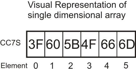
Below a visual sample of 1D character array.


Now for some explanation on 2 and 3 dimensional character array.

They work similar to their numerical partners except the last element defines the width of the string field. Ex.

char dow[7][4] = {“Mon”, “Tue”, “Wed”, “Thu”, “Fri”, “Sat”, “Sun”);

This means, create an array of 7 rows, 4 characters each.

Below the visual display of the above declared 2D array.


To display Friday I would need to specify the row element only. Example:

lcd_out(1,1,dow[4]);

Will display Fri on the lcd.

Similarly, 3D character arrays work the same way.

3D character array are declared as shown below.

char students[3][2][7] =

{“9w2bpy”, “Yau”,

“9w2dtr”, “Dexter”,

“9m2cf”, “Chow”};

Which will look like this.

This means declare a character array called students 3 rows 2 columns which can hold 7 characters each. Always remember to allocate space for the NUL character. If I did this:-

char students[3][2][7] =

{“9w2bpy”, “Yau”,

“9w2dtr”, “Dexter”,

9m2cf”, “Uncle Chow”};

The complier will generate an error, because “Uncle Chow exceeds 7 characters.

Alternatively I could do this :-

char students[3][2][] =

{“9w2bpy”, “Yau”,

“9w2dtr”, “Dexter”,

“9m2cf”, “Uncle Chow”};

Let the compiler check for the max length of string.

lcd_out(1,1, students[1][0]); // will output 9w2dtr.

lcd_out(1,1,students[0][1]); // will output Yau.

So, important thing to remember is that character arrays is :-

Remember to allocate 1 extra character for NUL.

The last [] specifies number of characters.

All arrays, be it character or numerical, elements number (the numbers between []), can only be unsigned integer (no negative and no decimal point values).

Sunday, May 11, 2008

Answers 4

Lesson 4 Skill Check Answers


Q1

Q2a

Q2b

Q2c

3

4


These are sample code for common cathode. All code using to display or blink the dot, can be XOR with 0x80 will on or off the dot regardless of of common anode or cathode.

Saturday, May 10, 2008

Multidimensional Arrays

Lesson 4.2


2 Dimensional (2D).

By now, you should have an understanding how arrays work. The element number points to the data stored. I will briefly now explain 2D and 3D arrays. These are known as multidimensional array. You can have as many dimensional as you need, but make sure you have enough memory to store them.

Let’s say I want to collect temperature reading in degrees C, 3 times a day, at dawn, noon and dusk for 7 days. This is how I would declare my array:-

float TempC[7][3];

This will look like a small spreadsheet. 2D arrays are reference in row and column format. So TempC will have 7 rows and 3 columns as illustrated in the diagram below.


I could also do this:-


float TempC[3][7];


Which would look like:-

You can use any method as long as you take care in storing and accessing the data. It is the norm to use the first method.

No special attention is needed to initialize the array. I would do the following for easier reading.


int table[4][3] =
{1, 2, 3,
2, 4, 6,
3, 6, 9,
4, 8, 12};

It just makes it easier to understand the way the data in the array is stored. It would not be wrong to do this:-

int table[4][3] = {1, 2, 3, 2, 4, 6, 3, 6, 9, 4, 8, 12};

if I wanted to print the array on lcd:-

Lesson 4.3

3D

Now I want to record temperature 3 times a day morning, noon and dusk; for the whole year. I could declare the array as float TempC[365][3]. This way I would not know the month and date the temperature is recorded for. A better way to do this would be float TempC[12][31][3], which would look like:-

Looks confusing? Let me explain,

Each row from 0 to 11 is month which is [12];

Each alternate color column is day which is [31];

Each day column (0, 1 and 2) is time of day the temperature is recoded is [3].

To store / and retrieve data from 3D array:

You can have as many dimensions that you need, but must take care of how much memory you have available. Example if you have an array of char sample[100][100][100], that is 1,000,000 bytes. Programming on a PC is OK but not for PIC.

Therein is a brief explanation on 3D arrays. If you do not understand, do not hesitate to leave comments us. Hope you have all understood the use of arrays. Next, I will explain a different kind of array in the next topic.

Monday, May 5, 2008

ADC scaling explained...

There seems to be some confusion regarding ADC scaling requirement so here are some examples why and how you would do it...

Example No 1: Voltage to be measured is higher than 5V...
Do take note that PIC ADC has a maximum input of VDD (+5V) thus if you want to measure voltage higher than 5V, you need to do some scaling of the actual voltage before it gets into PIC. Easiest way is to use a voltage divider using resistors (for more demanding applications, an opamp-based circuit may be required).

Lets look at an example. Assuming you want to measure the automotive battery voltage. Typically, the battery voltage will be between 11V (standby) and 14V (charging). For safety reason, let's assume we design for 20V maximum input voltage (25% safety factor). To accomplish this, we'll use 4 resistors of 4.7k each... a potentiometer can also be used to set it correctly. Wire the resistors as shown below:
In the above circuit, when a 20V voltage is present at the input, input to the ADC will be 5V... a 10V input will result in 2.5V input at the ADC... thus, the input voltage has been scaled by factor of 1/4. The ratio is obtained from the voltage divider... check some references if you not sure why this is so... :-)
Voltage at PIC ADC Input = Actual Input x (R1 / (R1+R2+R3+R4))

Assuming you use VDD (5V) as the ADC+ reference, the ADC reading will be 1023 when the ADC input is 5V (actual input of 20V). So, to get the actual voltage reading, you need to calculate it as follows:

Actual Voltage = ADC Reading * Designed Maximum Voltage /1024. Putting the actual numbers in, Actual Voltage = 1023 * 20 /1024 = 19.98V. The small difference is because the 10-bit ADC maximum value is 1023 instead of 1024...

Under this scenario, the maximum resolution is 20V/1024 = 19.5mV.

I'll post another example for expanded ADC resolution later...

Monday, April 28, 2008

Arrays


Single Dimensional (1D).


Key in the code below. I know it is long…But there is a point to this. This is to show you how to eliminate redundant code. After keying in the code and compiling it and correcting your typing errors; burn it to your PIC. Connect a common cathode (or common anode) 7 segment LED to portB. When the PIC is powered up, you will see the number 0, 1, ..9 displayed in a endless loop.


Lesson 4 Ver 1 Page 1

Lesson 4 Ver 1 Page 2

Lesson 4v1 compiled


Actually this is an example of bad programming. The code is large, it’s time consuming and the chances of making typos is high. I will now demonstrate arrays. This is how to define arrays:-

char name[30]; //This is an array of 30 characters.

double tempC[10]; // Array of 10 floating point numbers

int x[5]; // An array of 5 elements that can hold 5 signed int.

It like defining 5 variables.
x[0] can store a value x[1] can store another and so on.
x is a variable or const, and [0] is the location where the value is stored.


Also important to note:

the [] in arrays do not mean optional, as it usually does in documentation standard.
the first element of array is always 0.
arrays can be of any valid C data type, ie, float, double, int or char.


If you want to load the array with known values, do this when you declare you array:-

char base2[6] = {1, 2, 4, 8, 16, 32};

This array holds 6 elements, base2[0] is 1, base2[1] is 2, etc. etc. etc..

Or you can do this:-

unsigned int base2[]={1,2,4,8,16,32,64,128,256,512,1024};

When you don’t specify number of elements, and when you compile the, compiler will count then number of element and assign 0 to the first element, 1 to the next one and so on.

Following me so far….Excellent!

Firstly let’s use a variable cc7s as an array of chars. I set is as constant because the values will not change.

The point to this is that the code can be modified using arrays. Using the same code (new project, copy and paste), then change with the modifications in listing below.


Lesson 4 Ver 2 Page 1

Lesson 4v2 compiled


OK, All i have done is replaced the variables with arrays and if() with case. Some what smaller code. But wait! I see a pattern! when count==0, cc7s[0] is displayed, when count==1, cc7s[1] is displayed and so on. Then it loops back and starts over. So, lets redo the Version 1 and 2 code. Type in the listing below.

Note: switch..case will be explained in a later chapter..


Lesson 4 Ver 3 compiled


And that my dear students, is how you use arrays. It compiled to 83 bytes, as compared to 395 bytes in version 1. That’s almost 5 times smaller.


Let’s see if you understood the above lesson.

Skill Check!

1. Declare an array called DOW and initialize it’s elements with first 3 characters of day of week beginning with Monday.

2. What would need to do:-

a) To display decimal point with ALL the numbers.

b) To display decimal point ONLY with odd numbers.

c) To display decimal point ONLY with even number.

Only display decimal point, not to blink it.

Hint: You’ll need to refer to previous lessons.

3. Write a program to display number from 0 to 9 in an endless loop. Turn on the decimal point for 150ms and then off it for 150ms for every number.

4. Without changing the values of the arrays in the version 3 program, modify the program to display the numbers from 0 to 9 on a common anode 7 segment LED. (If you are already using a common anode, then do for common cathode).

Hint: Common cathode is opposite of common anode.

Wednesday, April 23, 2008

Let's C... Some ADC... 4U2C...


Updated:

After some of you got a little sober after the smooth operator 60s' twists, here's an an example of ADC usage in MikroC.

The codes are commented so you should roughly knows what the codes is all about and what each line is doing. I'll do a write up on ADC on the next post. In most cases, some form of scaling is required so some understanding of ADC reference voltage is crucial.

How the board is wired up for the lesson... noticed the purposed-built LCD ribbon cable?

Update 080425: A short brief on ADC.
PIC18F4550 (and most ADC capable PIC) has a 10-bit ADC core. The ADC is based on analog reading between VRef- to VRef+. When input is at VRef-, the value returned will be 0 (zero) and when input is at VRef+, the value returned will be 1023 (2^10 - 1, i.e., 2 to the power of 10 minus 1).
In the current example, via setting done with ADCON1, VRef- is set to VSS (GND) and VRef+ is set to VDD (+5V). Under this environment, the resolution of the ADC is +5V/1024 = about 5mV. When the potentiometer is at minimum (0V) the result is 0 and when at maximum (+5V) the result is 1023. To get the actual voltage reading, you need to do scaling, the math as follows:
Actual Voltage = (ADC Reading * Value at VRef+) / 1024
i.e., if result is 512, then the actual voltage is 512 * 5 / 1024 = 2.5V

If you need higher resolution, you can provide the PIC with your own VRef- & VRef+ directly to the AN2 & AN3 pins. Change ADCON1 settings to 0b00111011. If you set VRef+ to about 1V, the resolution becomes 1mV (1V/1024).

For quick reference, ADCON1 setting information is below:

On PIC18F4550, the analog pins are on 3 separate ports... do your own searching below... Remember to set TRISA, TRISB, TRISE and ADCON1 configuration accordingly...

Smooth Operators

Relational operators.

Relational operators are used indecision making. There are 6 different type of operator at your disposal. They are:-

Op

Comment

==

is equal to

!=

not equal to

<

less than

<=

less than OR equals to

>

more than

>=

more than OR equals to


These operators are used in loops, if(), while, for() or where ever is decision needs to be made. Take care when using this. Example if you want the loop to perform 4 cycles, writing a for loop for example:

for (x=1; x<4; x =4;x++); This only preform 3 iterations (loops), because when x=4, the condition will be false. 4<4, No 4 is equal to 4. So to overcome this problem, use x<=4 or x<5. This will achieve the result you want of 4 loops

Bit operators

&

AND

|

OR

~

NOT

^

XOR

>>

Shift right

<<

Shift left


How this works is as follows, variables alpha, bravo and result used.

alpha=0b10101010
bravo=0b11000110
result=0;


AND
result=alpha & bravo;

10101010 alpha
11000110 bravo
-------------
10000010 result
========

Only when BOTH values are 1 is the result 1. Similar to multiplication.


OR
result = alpha | bravo;

10101010 alpha
11000110 bravo
------------
11101110 result
=======

When EITHER values is 1, is the result 1. Similar to addition.


NOT
result= ~alpha;

10101010 alpha
------------
01010101 result
=======

When bit is 1 then result 0, when bit is 0 result 1.


XOR (exclusive OR)
result=alpha ^ bravo;

10101010 alpha
11000110 bravo
------------
01101100 result
========

When BOTH values 1 OR, BOTH values 0, result 0. When either value 1 AND 0, result 1.


Shift right
result=alpha >> 2;

10101010 alpha
------------
00101010 result
========

Moves 2 bits to right and replaces left most bits with 0.


Shift left.

result=alpha << 3

10101010 alpha
-----------
01010000 result
=======

Moves 3 bits to left and replaces right most bits with 0.


Boolean operators.

There will come a time, you will need to check on more and one value to make a decision. In your program you could do this:-

if (portb.f4==1) {
if (portc.f2==1) {
.
do processing.
.
.
}
}

This code will check if portb.f4=1 then check if portc.f2 = 1 then process the lines below it.

Another way of doing this will be by using a Boolean operator.

if (portb.4==1 && portc.f2 ==1) {

do processing1;

}

else {

do processing2;

}


The && is a Boolean AND

||

OR

TRUE when EITHER condition is true

&&

AND

TRUE when BOTH/ALL condition true

!

NOT

TRUE when FALSE


There are 3 Boolean operators, they are:

Using OR

if(var1==3 || var2 ==4 || varN==”CLS”) {

If either condition is true, process code below the if.

Using AND

if(var1==3 && var2==4 && varN==”CLS”) {

Only when all condition are true, process code below the if.


Using NOT

if (!EOF) {

if not end of file process code below if.


Assignment Operator

The single equal sign (=) is an assignment operator and assigns a value to a variable or constant (aka lvalues) AND is not a and used for comparison. Common mistake.

Ex.

if(portb==128) ….checks if portb is equal to 128

portb = 128; … assigns the value 128 to portb.

name[] = “9w2gu”

error = 255

const int ms=50;


Math operators

We all know how to do math right? We all know what + - * / % means.

But wait! What is * / %, not in my math book!

* is multiplication

/ is division

% modulus (remainder value)

Now you want to perform calculation on 3 numbers.

3 * 2 + 1;

Though not wrong (but not the answer you wanted), and answer will be 7, but the () should be used to group the calculation. (3 * 2) + 1 = 3 * 2 +1.

If I type 1 * 2 + 3 the answer now will be 6. This is because multiplication has a higher precedence than addition. So if you wanted to add then multiply,

then 3 * (2 + 1) = 9. If there are many ( ) within a formula, the inner most group of ( ) will be calculated first.

Ex.

result=2*(24/x-(3*y))

(3*y) is calculated first then 24/x. Then the subtraction and last multiplied by 2.


Monday, April 21, 2008

Quick Simulation on MikroC...

MikroC can do software simulation to check your codes... I'll show the basic method below...

To start with, make sure the debugger is set to "Software Simulator". It's on the lower left hand side of the screen. The other option is for MikroC custom-made ICD2 equivalent... Unfortunately, MikroC does not support the ICD2 from Microchip... their way of making extra buck by requiring you to buy their ICD2...

Then, you start the Debugger by pressing F9 or use the menu or the icon... Icon is on the right hand side... the one with the green arrow pointing downward...

Once the debugger started, a Watch window will open... this is you view toward everything... basically you select the variable you want to see, from the list, then click 'Add'...

After you click 'Add', the variable selected, in this case PORTB, will appear in the watch window. Click on the '0' next to PORTB and a small icon will appear next to the '0'. Click that icon to bring up the viewing option... In this case, just select binary... using binary, we can see how the bits look like...
After clicking OK, you're back to the watch window... Press 'F8' to step through your code... you'll see a blue bar highlighting the next instruction to be executed... PORTB value will change accordingly...

That's it... you've just simulated your code... if it work in the simulator, it stands very good chance to work in the actual circuit...

Sunday, April 20, 2008

Exercise 1: My way...


Different approach... same result... mainly to show that in programming, there is no right way or wrong way... just either more compact (less codes space) or faster execution... This code compile to 206 bytes only as opposed to over 1000 bytes on 9w2dtr version...